Guide – How to: integrate a third-party accelerator (e.g. NVDLA)
Latest update: 2021-08-09
ESP offers several design flows for designing accelerators, see for example the tutorials on how to design an accelerator in SystemC, in C/C++ and in Keras/Pytorch/ONNX. In many cases however, one may want to reuse an existing accelerator (i.e. a third-party accelerator), rather than designing a new one with ESP.
This tutorial explains how to integrate a third-party accelerator in ESP and, once integrated, how to seamlessly design an SoC with multiple instances of the accelerator and test it on FPGA. As a case study we use the NVIDIA Deep Learning Accelerator (NVDLA).
NVDLA
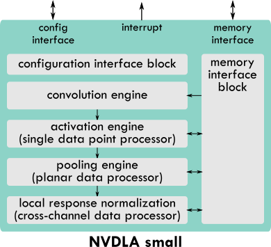
NVDLA is a deep learning accelerator from NVIDIA. It’s open source (nvdla.org), fixed function and highly configurable. NVDLA is composed of multiple engines needed to perform deep learning inference (e.g. convolution, activation, pooling, etc…). NVDLA has a configuration interface (APB) through which a host processor writes to a large set of memory-mapped registers. Once configured, NVDLA exchanges data with the memory hierarchy through a memory interface (AXI4). As soon as it completes the task, NVDLA notifies back the host processor by raising an interrupt signal. This is a very common invocation model for loosely-coupled fixed-function accelerators and it’s pretty much the same as for the ESP accelerators.
Although NVDLA is highly configurable, the NVDLA Compiler supports only a few configurations, named NVDLA full, NVDLA large and NVDLA small. To test and evaluate the integration of NVDLA in ESP, we use the NVDLA small, which has an 8-bit integer precision, 64 multiply-and-accumulate units, 128 KB of local memory and a 64-bit AXI4 interface.

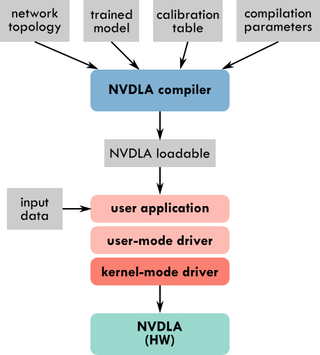
The NVDLA Compiler takes as inputs the network topology in prototxt format, a trained Caffe model, a calibration table needed for adjusting the network model (trained in full precision) to work with reduced precision, such as 8-bit integer precision in the case of NVDLA small. The NVDLA Compiler produces an NVDLA Loadable containing the layer-by-layer information to configure NVDLA. The NVDLA runtime leverages the user-mode driver to load the inputs and the NVDLA Loadable and to submit inference jobs to the kernel-mode driver, that is a Linux device driver.

There are many pairs of Caffe trained model and prototxt network topology available online (Caffe Model Zoo by Berkeley), however, we found that the NVDLA compiler can parse successfully only a small number of them out of the box. Working with the 8-bit integer precision of NVDLA small requires the additional step of generating the calibration table, the instructions for that are available in the NVDLA sw Github repository. With TensorRT it’s possible to generate the calibration scales to compensate for the reduced precision.
For the purpose of this tutorial we will use a LeNet network trained for the MNIST dataset. We have experimented with a few other networks, including ResNet50, as described in our CARRV’20 paper. Here you can find the inputs for the NVDLA Compiler for the LeNet network:
- lenet_mnist.prototxt
- lenet_mnist.caffemodel
- lenet_mnist.json (calibration table)
A prebuilt version of the NVDLA compiler is available in the NVDLA
sw repository at the path
prebuilt/x86-ubuntu/nvdla_compiler. Move to the x86-ubuntu folder, place
there the prototxt file, the Caffe model and the calibration table and then run
the following:
./nvdla_compiler --prototxt lenet_mnist.prototxt --caffemodel lenet_mnist.caffemodel -o .
--profile fast-math --cprecision int8 --configtarget nv_small --calibtable lenet_mnist.json
--quantizationMode per-filter --informat nchw
The output file is a NVDLA Loadable called fast-math.nvdla, which we rename
lenet_mnist.nvdla. This is the loadable that we will use for the experiments
in this tutorial, together with an input image from the MNIST dataset:
All the steps down to the generation of the NVDLA Loadable are done offline. Instead, the user application, the user-mode driver (UMD) and the kernel-mode driver (KMD) are executed at runtime, and therefore in this tutorial they will run on FPGA on the Ariane core in an ESP SoC.
Integrate a third-party accelerator
Currently ESP can host third-party accelerators with an AXI4 master interface to send out memory requests (32-bit or 64-bit), an APB slave interface (32-bit) to be configured by a CPU and an interrupt signal. Moving forward we expect to extend the support to more bit-width options and bus protocols. First, we plan to extend the support to AHB and AXI Lite interfaces, since ESP already contains adapters for these bus standards. Then we could consider other popular alternatives, like TileLink from UC Berkeley, Avalon from Intel, CoreConnect from IBM and Wishbone from the OpenCores community.
Here are the step by step instructions to integrate a third-party accelerator in ESP. NVDLA is an example of a third-party accelerator already integrated in ESP.
-
Accelerator folder. Create a folder with the name of the accelerator at the path
<esp-root>/accelerators/third-party/<accelerator-name>. Then move into this new folder. The folder for NVDLA is<esp-root>/accelerators/third-party/NV_NVDLA. -
HW source files. Place the source code of the hardware implementation of the accelerator in a folder named
ip. In the case of NVDLA,ipis a Git submodule pointing to our fork of the NVDLA hw repository. -
List of HW source files. Create the files
<accelerator-name>.vhdl,<accelerator-name>.pkgs(for VHDL packages),<accelerator-name>.verilog,<accelerator-name>.sverilogand populate them with the lists of all the RTL files in theipfolder that need to be compiled. In the case of NVDLA all the sources are in Verilog, so the VHDL source files, VHDL packages and SystemVerilog files are left empty. -
SW source files. Place the source code of the software applications and drivers for invoking the accelerator in a folder named
sw. In the case of NVDLA,swis a Git submodule pointing to our fork of the NVDLA sw repository. -
List of compiled SW files Create the files
<accelerator-name>.umdand<accelerator-name>.kmdand populate them with the lists of the device drivers, executable files and libraries generated after compiling the software in theswfolder. Thekmdfile is for the kernel-mode drivers, while theumdfile is for the user space applications and libraries. Create the file<accelerator-name>.hostsand list the processor cores available in ESP that can run the accelerator’s software (currently you can choose amongariane,leon3andibex). The ESP SoC flow will not allow to instantiate the accelerator in an SoC with a processor not listed in the.hostsfile. -
Accelerator wrapper. Design a wrapper for the accelerator compliant to the interface of ESP, using the
NV_NVDLA_wrapper.vas an example. The wrapper doesn’t implement any logic, its purpose is to adapt the accelerator interface to the signals naming convention that ESP expects. -
Accelerator description. Describe the accelerator in an XML file. Follow the XML for NVDLA as an example (
NV_NVDLA.xml). These parameters match the content of the accelerator wrapper (NV_NVDLA_wrapper.v)name: should match the name of the accelerator folderdesc: arbitrary and concise description of the acceleratordevice_id: unique hexadecimal device ID in the range 0x040 - 0x3FF. Make sure not to use the same ID for any other acceleratoraxi_prefix: prefix added to each AXI port in the accelerator wrapperinterrupt: name of the interrupt output portaddr_width: bit-width of the AXI address fieldsid_width: bit-width of the AXI transaction ID fieldsuser_width: bit-width of the AXI transaction USER fieldsclock: one entry for each clock port that will be connected to the ESP accelerator tile clockreset: one entry, including name and polarity, for each reset port that will be activated when the reset of the ESP accelerator tile is active
Once again, as an example, you can see the relationship between the entries in
NV_NVDLA.xml and the ports in NV_NVDLA_wrapper.v.
-
Makefile. Populate a simple Makefile with two required targets:
swandhw.hwis used for RTL code generation, when that applies, like in the case of NVDLA.swshould cross-compile both user-space applications and libraries (umd) and kernel-space drivers (kmd). The Makefile variables for the cross compilation are set by the main ESP Makefile and don’t need to be set in the third-party accelerator Makefile, these variables areKSRC,ARCHandCROSS_COMPILE. We recommend to follow the NVDLA example. -
Vendor. You also have the opportunity to specify the vendor of the accelerator by creating a file called
vendorcontaining only the name of the vendor. -
Additional description. The only file to be edited outside of the newly created third-party accelerator folder is
<esp-root>/tools/socgen/thirdparty.py. This file specifies the device name to be used in the compatible field during the generation of the device tree and whether the interrupt of the third-party accelerator is edge-sensitive (0) or level-sensitive (1). The compatible field is a string generated as<VENDOR>,<DEVICE ID>. This string must match the corresponding compatible field in the open firmware data structure struct of_device_id of the device driver (i.e. the kernel module).
After these steps, the accelerator is fully integrated and ESP sees it the same way it sees any other accelerator.
Design and test an SoC with a third-party accelerator
Move into the SoC working folder for the FPGA board of your choice (e.g. the Xilinx Virtex Ultrascale+ VCU118 FPGA board).
cd <esp-root>/socs/xilinx-vcu118-xcvu9p
SoC configuration
Configure the SoC with the ESP mix&match floor-planning GUI. You can launch the GUI with:
make esp-xconfig
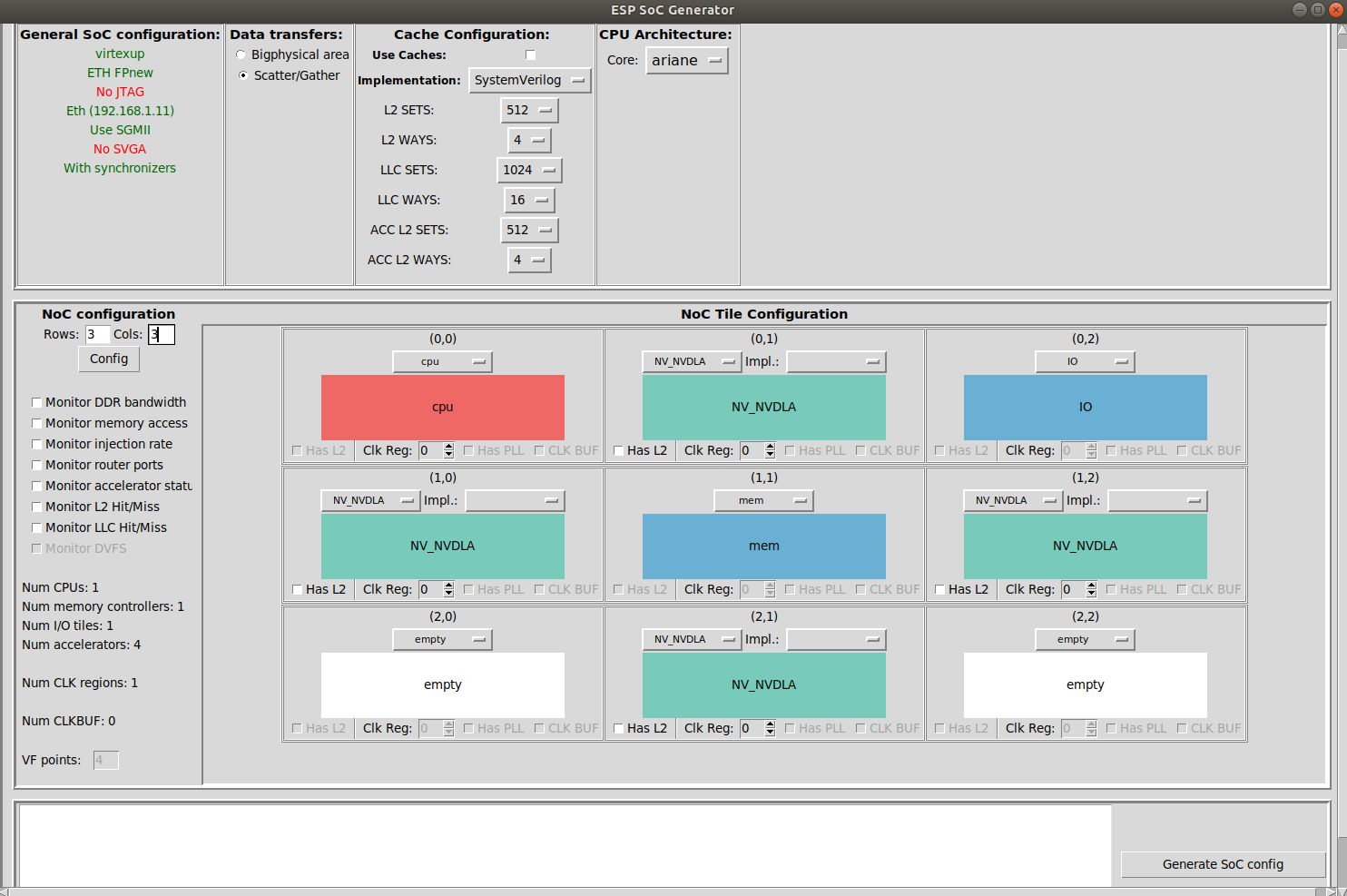
In addition to the usual processor tiles, memory tiles and ESP accelerator
tiles, now you can instantiate also third-party accelerator tiles. In the
drop-down menu of each tile you will find the option to choose NV_NVDLA, plus
any other third-party accelerator that may have been integrated.
For SoCs with the Ariane processor, only the accelerators with
ariane listed in
accelerators/third-party/<accelerator>/<accelerator>.hosts are
available for selection. The main reason for this is that in some
cases the accelerator’s software stack may only work with one of the
available processors in ESP. For example the software of NVDLA
currently works with Ariane only.
The memory interface of a third-party accelerator must have a 64-bit word width for SoCs with the 64-bit Ariane processor and a 32-bit word width for SoCs with the 32-bit Leon3 processor or the 32-bit Ibex processor. Even though we may relax this requirement in the future, those will remain the recommended bit-width values, because they match the default NoC width for the Ariane-based, Leon3-based and Ibex-based architectures respectively.
For this tutorial we configure the SoC as follows (remember to save with Generate SoC Config):

After closing the GUI you can check the Ariane device tree
(socgen/esp/riscv.dts) where you will find the NVDLA devices
that you instantiated with the GUI.
Recall the “Debug link configuration” instructions from the “How to: design a single-core SoC” guide. Everything described there applies whenever designing an SoC with ESP.
Third-party source code compilation
Both the NVDLA runtime application and device driver provided by NVIDIA only
work with a single instance of NVDLA. In our
fork of the NVDLA sw repository, we
modified the NVDLA UMD and KMD to support systems with multiple instances of
NVDLA executing in parallel. The maximum number of instances is currently set to
4, but you can increase it by changing the following constants:
// In kmd/firmware/dla_engine_internal.h
#define MAX_N_NVDLA 4

// In core/src/runtime/include/priv/Runtime.h
size_t getMaxDLADevices() { return 4; }
Build boot-loader and Linux image.
make linux [-jN]
Compile/build both the hardware and software source code of the third-party
accelerator.
make <accelerator-name> # e.g. make NV_NVDLA
This step copies the runtime executable (nvdla_runtime) and
library (libnvdla_runtime.so) as well as the device driver
(opendla.ko) into the root file system that will be deployed on
FPGA, namely the soft-build/ariane/sysroot folder.
Place the files
lenet_mnist.nvdla and
seven.pgm in
soft-build/ariane/sysroot/root/NV_NVDLA.
Every time something changes in the sysroot folder, the Linux image
needs to be re-generated.
make linux [-jN]
FPGA prototyping
Recall the “FPGA prototyping” instructions from the “How to: design a single-core SoC” guide. Everything described there applies whenever designing an SoC with ESP.
Generate the FPGA bitstream.
make vivado-syn
Program the FPGA and boot Linux.
make fpga-program
make fpga-run-linux
Observe the boot through a serial communication program (e.g. minicom). Optionally after the boot you can SSH into the ESP instance on FPGA instead of interacting with it through the serial communication program.
Toward the end of the boot the device drivers of all the accelerators get registered. You will see 4 NVDLA devices registered like in the picture below:
[   33.479107] Probe NVDLA config nvidia,nv_small
[   33.526396] [drm] Initialized nvdla 0.0.0 20171017 for 60400000.nv_nvdla on minor 0
[   33.695024] 0 . 12 . 5
[   33.703127] reset engine done
[   33.733930] Probe NVDLA config nvidia,nv_small
[   33.775771] [drm] Initialized nvdla 0.0.0 20171017 for 60500000.nv_nvdla on minor 1
[   33.944645] 0 . 12 . 5
[   33.952729] reset engine done
[   33.977915] Probe NVDLA config nvidia,nv_small
[   34.019091] [drm] Initialized nvdla 0.0.0 20171017 for 60600000.nv_nvdla on minor 2
[   34.184605] 0 . 12 . 5
[   34.192690] reset engine done
[   34.217802] Probe NVDLA config nvidia,nv_small
[   34.257816] [drm] Initialized nvdla 0.0.0 20171017 for 60700000.nv_nvdla on minor 3
[   34.424548] 0 . 12 . 5
[   34.432611] reset engine done
After logging in (user: root, passwd: openesp) move to the accelerator folder.
cd <accelerator-name> # e.g. cd NV_NVDLA
At this point you can execute the runtime application for testing the
accelerator. Of course each accelerator may have a completely different
application, so this step is specific to each accelerator. In this case we will
proceed by running the runtime application for NVDLA.
In the NV_NVDLA folder, together with the application executable
(nvdla_runtime) and the runtime library, you will find the LeNet NVDLA
Loadable (lenet_mnist.nvdla) and the input image seven.pgm.
You can execute inference on one specific instance of NVDLA thanks to the
--instance argument that we added to the NVDLA UMD.
  # Inference on instance 0
  ./nvdla_runtime --loadable lenet_mnist.nvdla --image seven.pgm --rawdump --instance 0

  # Inference on instance 1
  ./nvdla_runtime --loadable lenet_mnist.nvdla --image seven.pgm --rawdump --instance 1

  # Inference on instance 2
  ./nvdla_runtime --loadable lenet_mnist.nvdla --image seven.pgm --rawdump --instance 2

  # Instance on instance 3
  ./nvdla_runtime --loadable lenet_mnist.nvdla --image seven.pgm --rawdump --instance 3
Here is an example of the terminal output for running the LeNet inference
on one of the NVDLA instances: sample terminal
output.
output.dimg contains the classification results: MNIST has 10 classes
which correspond to the digits from 0 to 9. A correct classification for the
seven.pgm image would mean that the number in position 8 of 10 is the
highest. Run the following to see the classification results:
$ cat output.dimg
0 2 0 0 0 0 0 124 0 0
You can also run multiple inference jobs in parallel.
  # Instaces 0-1-2-3 in parallel
  ./nvdla_runtime --loadable lenet_mnist.nvdla --image seven.pgm --instance 0 & \
  ./nvdla_runtime --loadable lenet_mnist.nvdla --image seven.pgm --instance 1 & \
  ./nvdla_runtime --loadable lenet_mnist.nvdla --image seven.pgm --instance 2 & \
  ./nvdla_runtime --loadable lenet_mnist.nvdla --image seven.pgm --instance 3 &
By default both the NVDLA UMD and KMD print a lot of information. If the
KMD prints do not appear on screen, you can see them at the end of the execution
by running dmesg.
To silence all the debug and info prints by the KMD, you have to go back to the NVDLA compilation step.
  make NV_NVDLA-clean # do not skip this step
  VERBOSE=0 make NV_NVDLA
The runtime application reports the execution time, but all the terminal prints
make it inaccurate. To collect executing time data you may want to remove some
of the UMD prints as well.