This guide illustrates how to create an instance of ESP with multiple accelerators and how to develop an application that invokes them using the ESP API. We will focus on how to reconfigure at run time the coherence model for each accelerator invocation and how to setup point-to-point communication.
Platform support: The many-accelerator architecture and ESP software API are vendor independent, but this worked example generates its accelerators with HLS and its prebuilt material targets AMD/Xilinx boards. On the Intel/Altera DE10-Pro SX, use RTL or Third-Party accelerators and follow the board-specific build and payload-loading flow. That port is an unreleased development preview. Coming soon
For this tutorial, we assume that you are already familiar with the ESP build infrastructure and at least with the steps presented in the guide How to: design a single-core SoC. For better understanding, we recommend that you read the guide How to: design an accelerator in SystemC as well.
In this guide and in the corresponding prebuilt
material we use the example application multifft, which
drives three identical FFT accelerators. The example is based on the application
skeleton generated by the ESP automation flow when we implemented FFT in
SystemC. Differently from the basic unit test, however, this example invokes FFT
multiple times, each with a different configuration:
- Single FFT using non-coherent DMA
- Single FFT using LLC-coherent DMA
- Single FFT using fully-coherent DMA
- Three concurrent and independent FFTs, each using a different coherence model
- Three cascaded FFTs, each operating on the output of the previous one through point-to-point communication
Note: If you increase the number of samples processed by the FFT accelerators, the point-to-point test will fail the test. This is due to the error accumulation when applying fixed-point FFT three times on the same vector in place. You may try using the 64-bit fixed-point configuration of FFT to reduce the error rate. The HLS configuration can be selected from the ESP configuration GUI and can be different for each instance of FFT. If you select the 64-bit version of FFT, make sure you change the fixed-point configuration in the software application as well!
1. Multi-accelerator SoC
Generate accelerator RTL
Enter a working folder for one of the supported FPGAs.
cd <esp>/socs/xilinx-vc707-xc7vx485t
This tutorial leverages the FFT accelerator, which is designed in SystemC and
implemented with Cadence Stratus HLS.
Generate the FFT for the target FPGA by running the HLS target
make fft_stratus-hls
SoC configuration
Once HLS completes, the ESP configuration GUI will find the RTL available in two
flavors: fixed-point 32 bits (fx32) and fixed-point 64 bits (fx64). For this
tutorial please use the fx32 implementation, which is the default
configuration in the example test application.
Open the ESP configuration GUI.
make esp-xconfig
Select a NoC configuration of 2x3 or 3x2 and add three FFT accelerators, one Ariane processor core, one I/O tile and one memory tile. In order to test the coherence reconfiguration, we must enable the ESP cache hierarchy by enabling “Use Caches” in the cache configuration tab. For faster logic synthesis and to avoid another HLS run, use the “ESP RTL” implementation of the caches.
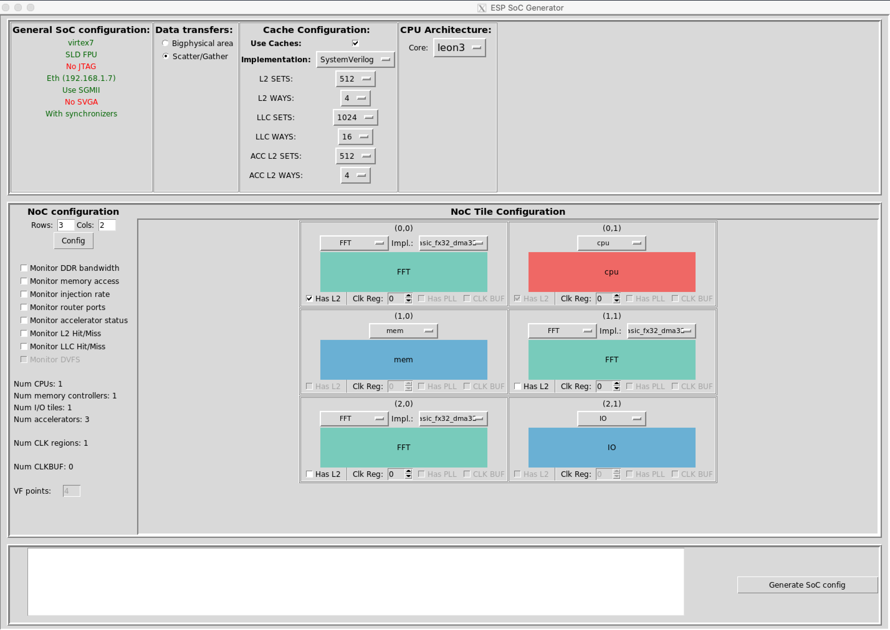
The location of the components in the system is irrelevant. Routing tables are generated based on the chosen configuration.
Note: the test application expects the FFT located in the tile with the smallest ID to have an L2 cache available. Tiles are numbered from left to right and then top to bottom. You may choose to enable the L2 cache for all three FFTs to explore even more software configurations.
Do not copy the bundled example configuration: In ESP 2026.1.0,
<esp>/soft/common/apps/examples/multifft/esp_configpredates fields in the current NoC configuration format. Create the three-FFT Ariane design in the GUI and review the generated.esp_configinstead.
Finally, you may launch logic synthesis with Vivado.
# From a clean working folder
make vivado-syn
2. ESP user-space API
Example application
The example application is located at the path
<esp>/soft/common/apps/examples/multifft.
First you should open and analyze the configuration header file
multifft_cfg.h. This file includes all run-time configurations that
we wish to execute using the ESP API. Each configuration is defined as
an esp_thread_info_t, which is an array of size corresponding to the
number of accelerators involved in a particular invocation. The
esp_desc field points to a structure containing the configuration
parameters for the FFT accelerator: struct fft_stratus_access.
For instance, the configuration cfg_parallel lists all three FFT
accelerators, with devname fft_stratus.0, fft_stratus.1 and
fft_stratus.2 respectively. This configuration runs all three
accelerators concurrently. The configurations cfg_nc, cfg_llc and
cfg_fc, instead, invoke just fft_stratus.0 and list only one
accelerator. The difference among these three configurations is the
coherence model selected: non coherent, LLC coherent or fully
coherent. Please refer to our ASPDAC 2019
paper to get
information about accelerator coherence in ESP.
The parallel configuration selects a different coherence model for each accelerator and then runs them all in parallel. The three accelerators operate on a different region in memory on independent data sets.
The last configuration, cfg_p2p, instead, configures accelerators to
operate in chain by using point-to-point communication. The first
FFT, fft_stratus.0, reads data from memory (.esp.p2p_nsrcs = 0 in
the structure the esp_desc field points to), but then sends the
result directly to another accelerator (.esp.p2p_store = 1). The second FFT,
fft_stratus.1, leverages point-to-point for both read and write
operations. Instead of requesting data from memory, it requests data
from fft_stratus.0 (.esp.p2p_srcs = {"fft_stratus.0",
"", "", ""}). Note that ESP supports a maximum fan-in of 4
accelerators for point-to-point communication. The last FFT,
fft_stratus.2, requests the data from fft_stratus.1, but then
stores the results back to memory.
Note: when using point-to-point communication, all accelerators in the chain must be configured to use the same coherence model. This can be non coherent, LLC coherent, or coherent with recalls, but not fully coherent. Point-to-point communication occurs without involving the cache hierarchy, thus the fully-coherent configuration cannot be used. Please refer to the DATE 2020 paper and the ASPDAC 2019 paper for more details.
The main application multifft.c is based on the FFT unit test. We have
extended such application by repeating the input data initialization,
the accelerator invocation and the output validation for every configuration
present in the header file.
The application reuses the same memory buffer for all configurations; that is we
only call esp_alloc() once. Depending on the test, we prepare the data for
one or three FFT accelerators. Similarly, the golden output is computed in
different ways, depending on how we intend to run the accelerators.
To run a configuration, we simply need to call esp_run(<cfg>, <number of
accelerators>). The ESP library spawns a thread for each accelerator, copies
the configuration into the accelerators registers and runs them in parallel.
Once all threads terminate, esp_run() returns to the caller, which can safely
run validation.
3. FPGA execution
Once logic synthesis has completed, compile Linux, the example application and prepare the bootable image.
# Compile Linux, drivers and libraries
make linux
# Compile example application
make examples
# Update Linux image
make linux
Open a UART interface and make sure that the esplink application can reach the
FPGA (How to: design a single-core SoC).
Now you can program the FPGA and run the Linux image
make fpga-run-linux
Once Linux boots, log in as root with the development password openesp, then
run the test application. Press Enter when prompted. These credentials are
public defaults; change or disable them before connecting the board to an
untrusted network.
cd /examples/multifft
./multifft.exe
Feel free to change the application and test additional configurations of the
three FFT accelerators. If you upload a new application with scp, keep the
board on a trusted, isolated development network.
FPGA prototyping with prebuilt material
With the provided prebuilt material, you can run the tutorial on FPGA directly. Each packet is marked with the first digits of the Git revision it was created and tested with.
The packet contains the following:
- Two working folders for Xilinx VCU118 and Xilinx VC707, each including:
- The Linux image (
linux.bin) - The boot loader image (
prom.bin) - The FPGA bitstream (
top.bit) - The hidden configuration files for the design (
.grlib_configand.esp_config) - A script to run the design on FPGA (
runme.sh)
- The Linux image (
Decompress the content of the packet from the ESP root folder to make sure all files are extracted to the right location.
cd <esp>
tar xf ESP_MultiAcc_GitRev.5f0f335.tar.gz
Enter one of the soc instances extracted from the packet.
cd socs/multi_acc_vc707
Follow the “UART interface” instructions from the “How to: design a
single-core SoC” guide,
then launch the runme.sh script
./runme.sh
Once Linux boots, log in as root with the development password openesp, then
run the test application. Press Enter when prompted. Change or disable the
public development credentials before using an untrusted network.
cd /examples/multifft
./multifft.exe